Electronic Design and Family Site
A Keyer for my main station
I recently realized I needed a keyer for my portable equipment. Building that reminded me that I didn't have any other keyer to use at my main station. Then, during this year's Sweepstakes Contest, the keying interface to my computer went intermittent. It nearly cost me the contest! Thus was born the idea to build a keyer into my main operating console.
My needs were fairly simple: The intermittent connection was due to the use of an RCA jack on the old interface that was built into a plug at the back of the computer. Instead, I wanted to move the interface to the console and use a serial cable to connect the computer to the console.
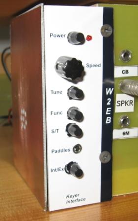
Then I wanted an actual keyer for use at the operating position. I wanted it to have switchable sidetone for those rigs without sidetone, and a "Tune" function to allow me to tune antennas. Finally, I wanted it built into my console...to look like it belonged there.
Schematic
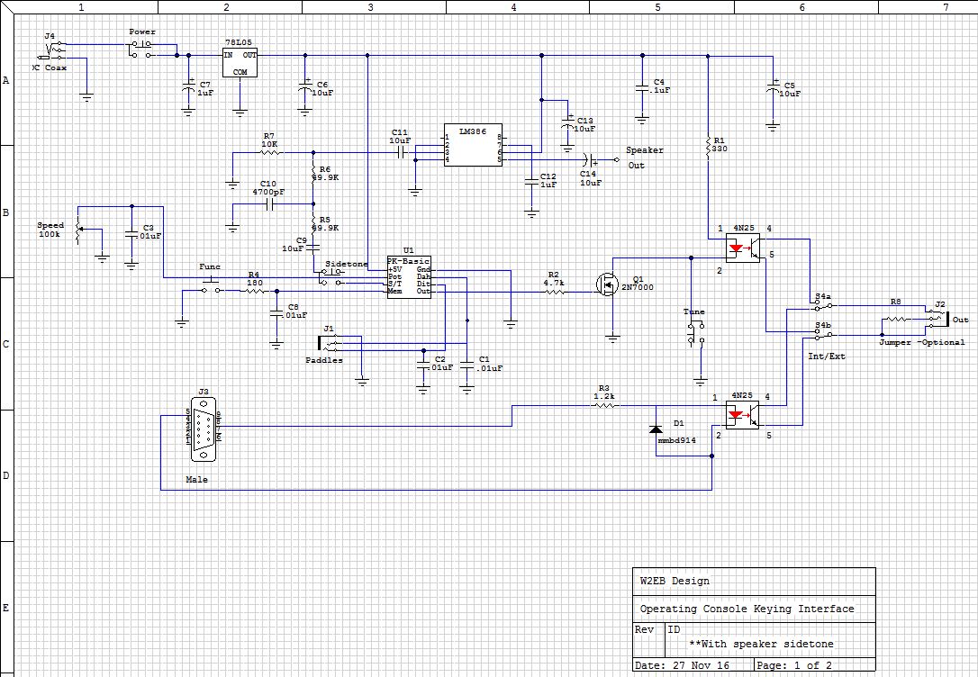
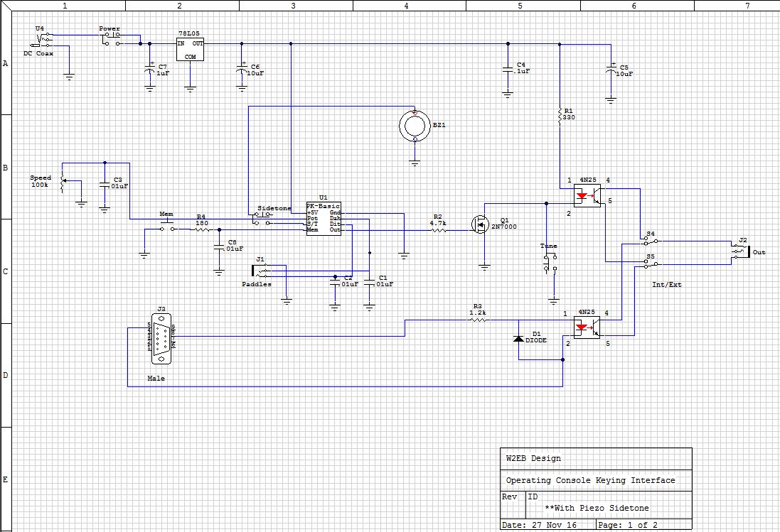
The schematic comes in 2 versions: with audio amp on sidetone, and without. Piezo buzzers vary greatly in their output volume, and I couldn't be sure the piezos I'd chosen for this project would work well, so I included the means of using a simple 8 ohm speaker and an audio amplifier if necessary.
The schematic for the computer keying comes straight from the website of the software designer N3FJP, and consists solely of a single resistor and single diode to feed an opto-isolator which feeds the keying input to the rig. I take the signal from pin 8 of the DB-9 vs. pin 7 of the original schematic, because my interconnect cable swaps those two pins.
The schematic associated with the keyer comes from the website of the keyer designer, WB9KZY, Jackson Harbor Press.
Operation is quite simple: incoming DC is switched and fed to an LED to show power status. The input DC is fed to a regulator that reduces the voltage to that which the Keyer IC requires, +5V. The paddles feed the keyer IC thru an 1/8" jack. The output of the keyer IC feeds a MOSFET that further feeds an opto-isolator to isolate the digital circuitry from the analog of the rig. The output can be enabled using the "Tune" switch which bypasses the MOSFET regardless of the keyer's output. Finally, sidetone can be switched on or off using the sidetone switch. The sidetone output of the keyer can either feed a piezo directly, or feed a speaker thru an audio amp with some R/C filtration.
The keyer has some internal settings that can be changed using the "Func"(tion) switch. Finally, the input method, computer or keyer IC is selected using the Int/Ext switch. **Note: I had a suitable Piezo, so the audio amp is untested. If you decide to use it, it MAY NOT WORK!
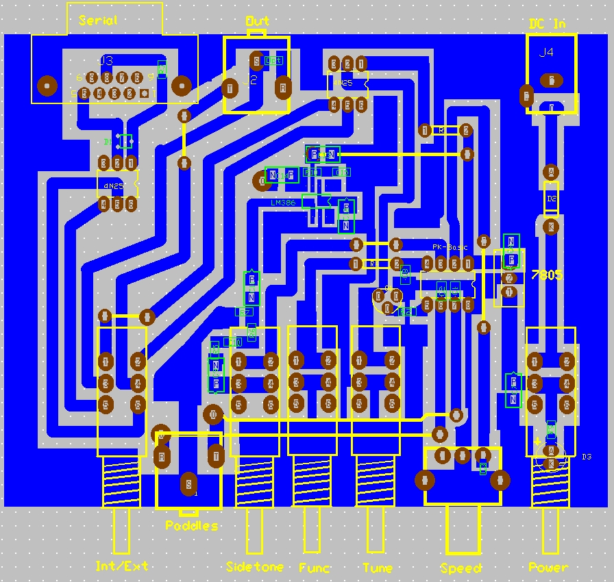
PCB Layout
The Piezo, if used, is soldered to the tabs on the top of two switches: Positive(+) is on center of the "Sidetone" switch, and Negative(-) is to the center of the "Tune" switch:
PCB Layout, Bottom Layer Only