
Electronic Design and Family Site
I Designed and made my own Integrated Circuit!!
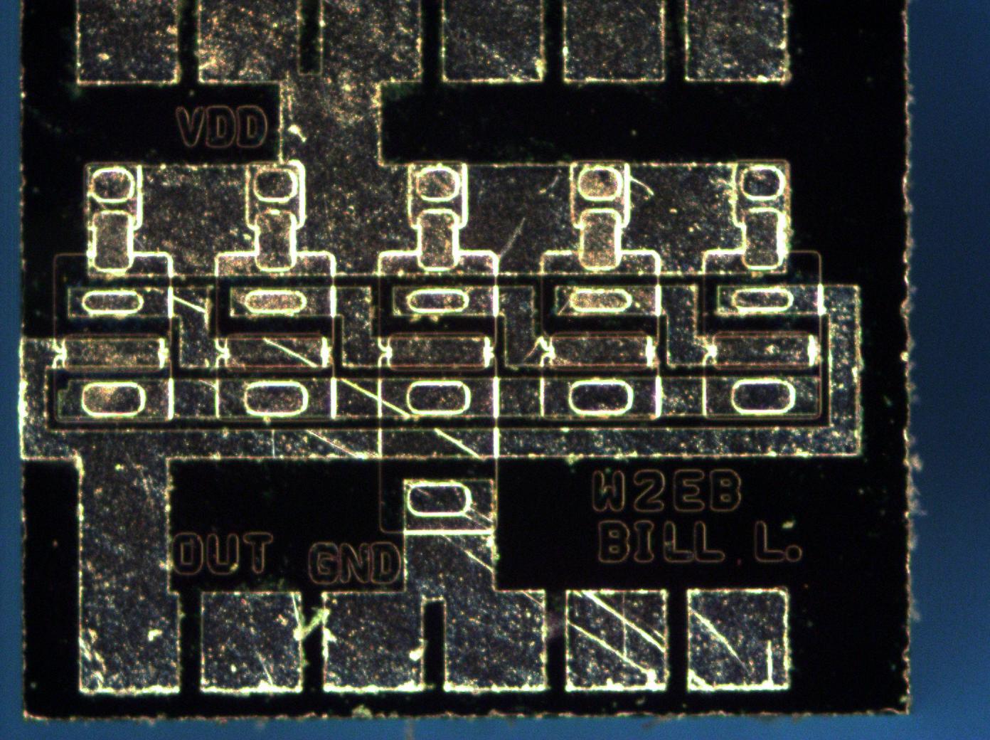
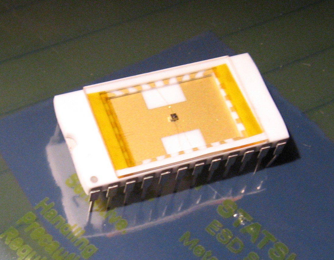
I work in a business that designs semiconductors; imagers to be exact. Since I had little background in the field, they sent me to an introductory course in IC design at the Rochester Institute of Technology (RIT). In that course, we combined a highly accelerated IC design and fabrication theory class with an actual hands-on lab where we each made our own IC. In 5 (long) days, we went from nothing to the chip shown above.
To put this in perspective, a panel of 64 ICs designed by members of the class fits on a die approximately .25" x .25". This IC is 850uM (.033") wide by 700uM (.028") tall.
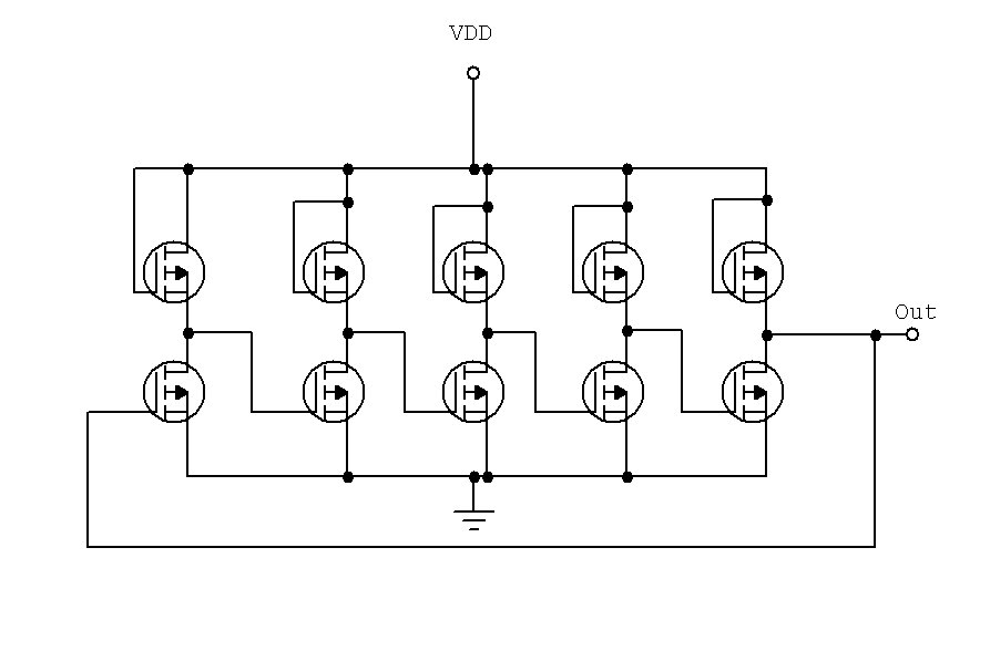
The schematic is really quite simple: each upper and lower pair of FETs is an inverter. The group of 5 inverters feed back onto themselves to force oscillation. The rate of oscillation is determined in part by the turn-on and turn-off delay of each inverter. Thus, more inverters equals a lower frequency.
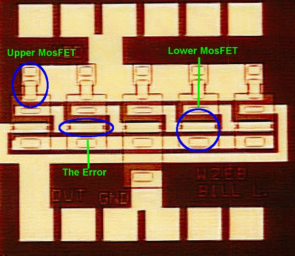
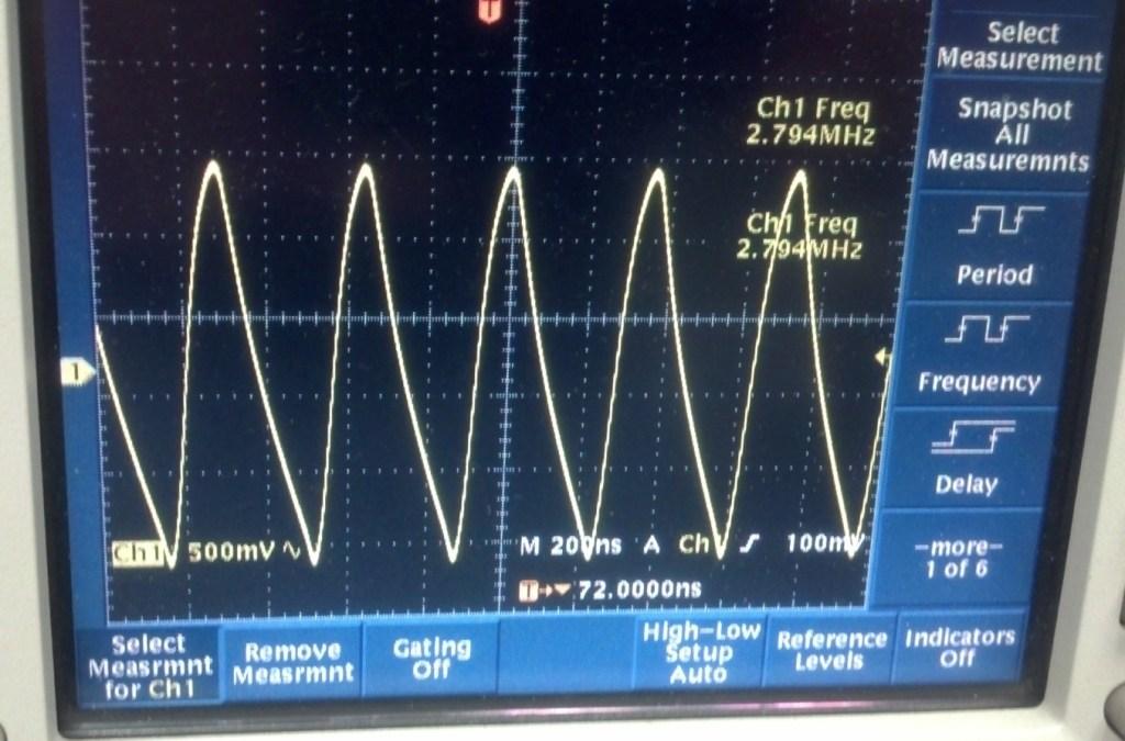
I made an error in the design of my IC: I violated a design rule about spacing between two diffusion layers. I initially thought that error was fatal; when we first fired up my device it wouldn't oscillate. Then we discovered that my device's output was also inadvertently tied to overall wafer substrate. An inventive co-worker of mine cut my circuit away from the rest of the wafer and it merrily oscillated at about 800KHz (with-5V applied). With -10V applied, it came up to a screaming 2.8MHz! It works very well and might possibly set a record for a 5-stage ring counter in this class.
I learned a tremendous amount in the course, and am very proud to be able to say:
I designed my own IC!
-Bill Lazure